Yesterday I finished a masterfully mind-bending, brain-melting science fiction book Permutation City – Greg Egan. This book made me ponder things I would have never otherwise contemplated, it transported me into a world of new possibilities. Without a doubt, the most thought-provoking science fiction book I’ve picked up, I am quite frankly still in awe. I would encourage anybody to read this, especially those involved in software.
The book inspired me to explore the various worlds of cellular automaton. The Game Of Life by John Horton Coway is the most well-known but in this blog, I’m going to delve into a more obscure automaton Wireworld.
Wireworld, alternatively WireWorld, is a cellular automaton first proposed by Brian Silverman in 1987, as part of his program Phantom Fish Tank. It subsequently became more widely known as a result of an article in the “Computer Recreations” column of Scientific American.[1] Wireworld is particularly suited to simulating transistors, and is Turing-complete.
You can find all of the code used in this blog on my GitHub.
Rules
In a 2 dimensional grid each cell can be in 1 of 4 states varying in colours:
- Empty
- Electron head (blue)
- Electron Tail (red)
- Conductor (yellow)
On each program tick the cells change depending on their current state:
- An empty cell is always empty, it will never change
- An electron head will change to an electron tail
- An electron tail will change to a conductor
- A conductor will change to an electron head if exactly one or two of its neighbour cells are electron heads, otherwise, it remains a conductor.
Code
Assuming we have the basic building blocks of a grid etc, on each tick, we need to create the new generation of cells following the basic rules above:
function createNewGeneration() {
  let nextGeneration = createGrid();
  for (let i = 0; i < columns; i++) {
    for (let j = 0; j < rows; j++) {
      if (grid[i][j] == 0) {
        nextGeneration[i][j] = 0;
      } else if (grid[i][j] == 1) {
        nextGeneration[i][j] = 2;
      } else if (grid[i][j] == 2) {
        nextGeneration[i][j] = 3;
      } else if (grid[i][j] == 3) {
        let electronNeighbours = countElectronNeighbours(i, j);
        if (electronNeighbours == 1 || electronNeighbours == 2) {
          nextGeneration[i][j] = 1;
        } else {
          nextGeneration[i][j] = 3;
        }
      }
    }
  }

  return nextGeneration;
}
And the countElectronNeighbours function looks like this:
function countElectronNeighbours(x, y) {
  let sum = 0;
  const neighbours = [
    [-1, -1], [-1, 0], [-1, 1],
    [0, -1],         [0, 1],
    [1, -1], [1, 0], [1, 1]
  ];

  for (let neighbour of neighbours) {
    let newX = x + neighbour[0];
    let newY = y + neighbour[1];

    if (newX >= 0 && newX < grid.length && newY >=0 && newY < grid[0].length) {

      if (grid[newX][newY] == 1) {
        sum++;
      }

    }

  }

  return sum;
}
Let’s set the initial world state to be a simple wire, so a line of conductors with an electron head and tail:
 for (let i = 0; i < 10; i++) {
    grid[15 + i][10] = 3;
 }

 grid[16][10] = 2;
 grid[17][10] = 1;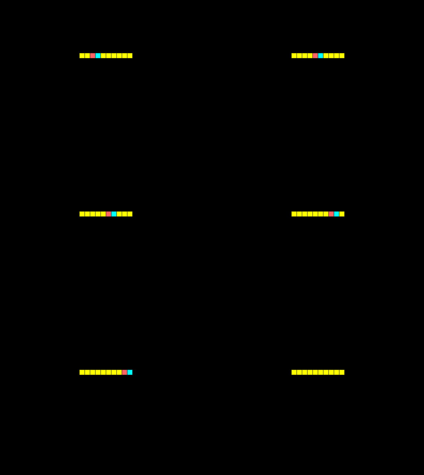
Awesome, we now have an electron moving across a wire, let’s make it a rectangle and up the tick rate.
  for (let i = 0; i < 10; i++) {
    grid[15 + i][10] = 3;
    grid[15 + i][15] = 3;
  }

  for (let i = 0; i < 5; i++) {
    grid[15][10 + i] = 3;
    grid[24][10 + i] = 3;
  }


  grid[16][10] = 2;
  grid[17][10] = 1;
Clocks
Okay, let’s have some fun, let’s build a clock. A clock can generate a signal to be pushed down the wire every second or so. I’ll use this for the next few examples so it’s important to understand:

Diodes
In electronics diodes are very important, they only allow current to flow in one direction. We can easily replicate this in Wireworld with the following circuits.

Notice how the electricity can pass through the top diode, but not the bottom — flipped — diode.
OR gates
The simplest logic gate in Wireworld is the OR gate. An OR gate must have one of its inputs high for the output to be high:
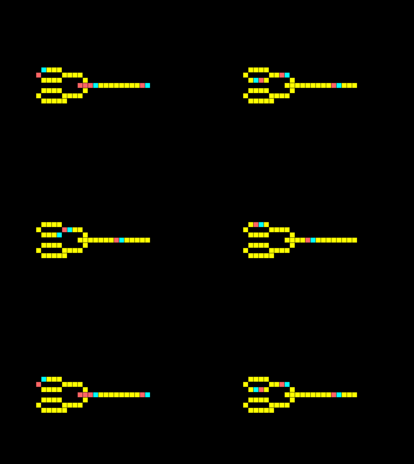
For the example above I’ve not enabled the bottom signal generator. Below I’ve enabled both signal generators to show that if both input signals are high the output is high.
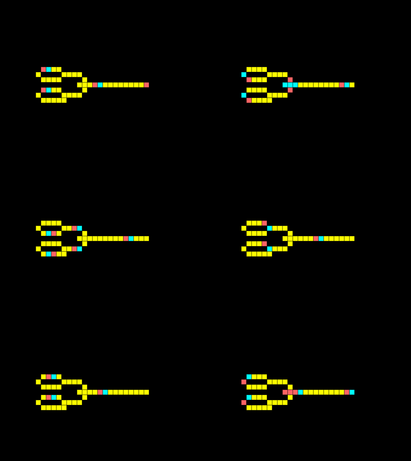
AND gates
A fundamental logic gate is the AND gate. The logical AND gate is written as AB in Boolean algebra. The result is true only if both A and B are true. In the example below there are 2 inputs, and 1 output, notice how there is a signal on both lines so we get an output:
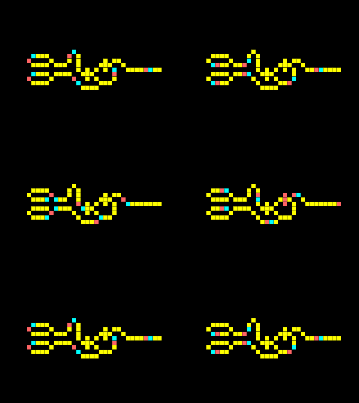
Look at what happens if we remove the connection for one input:
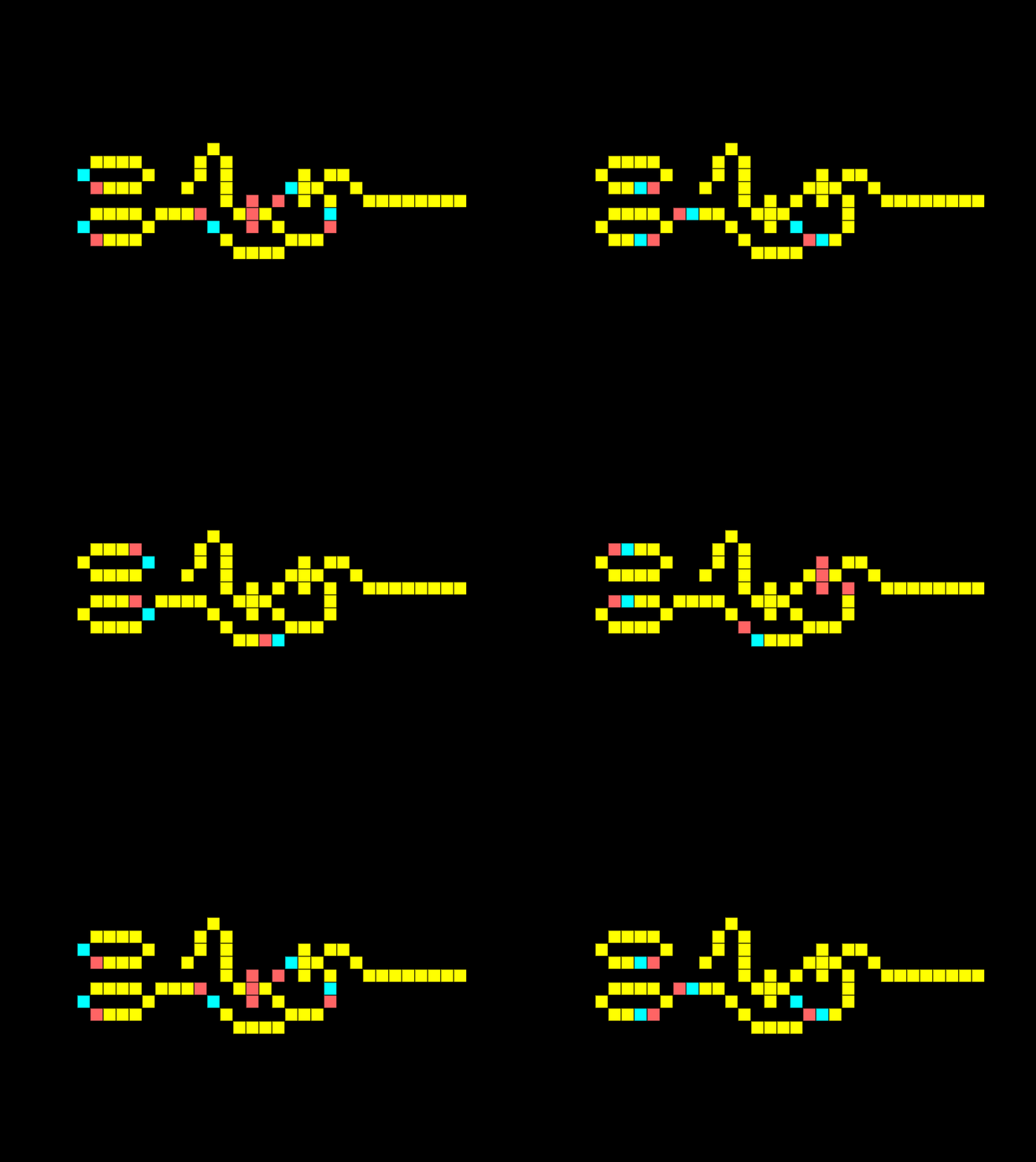
The output is off as a signal from both inputs is required simultaneously. The same would occur if the signals were offset.
XOR Gate
An XOR gate only has an output if one input is received, but not both. Notice how below the two signals meet and cancel each other out:
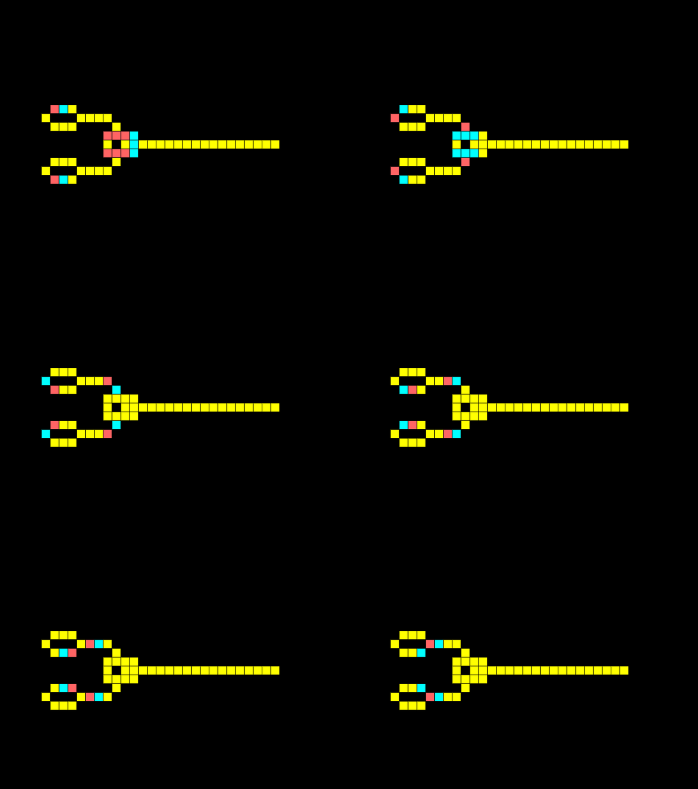
If I remove one of the signals, we get an output:
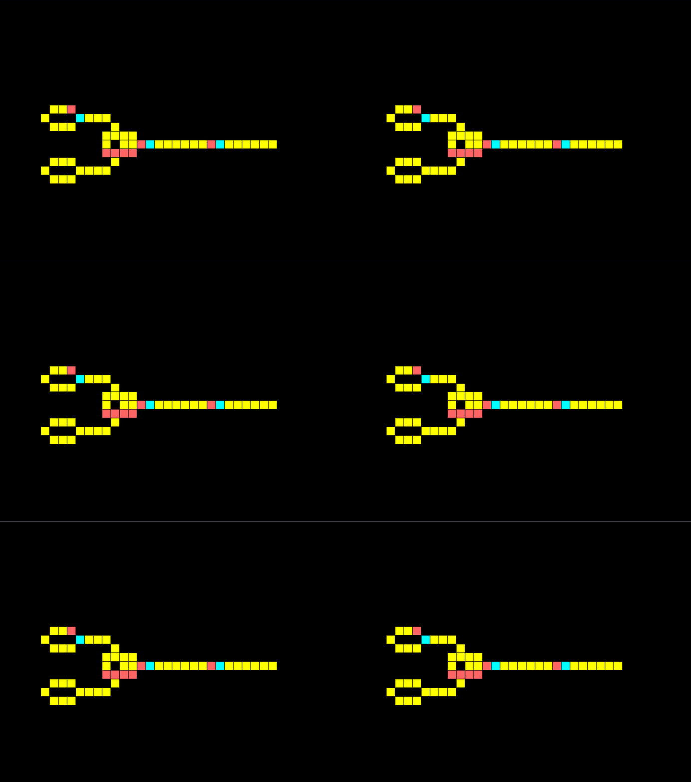
With these gates, I should have enough to create a half-adder.
Half-adder
A half-adder is a fundamental building block of a computer, it allows us to sum two binary digits A and B.
When a single input is on the output should be 1 meaning binary 0+1=1. Notice in the half adder below only the XOR is giving an output:
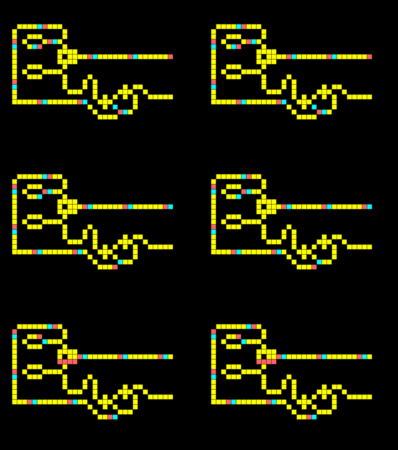
When both inputs are on in a half adder the output should be 10, meaning two binary values of 1 added together equal 10. Notice how the XOR output is low whilst the AND output is high.
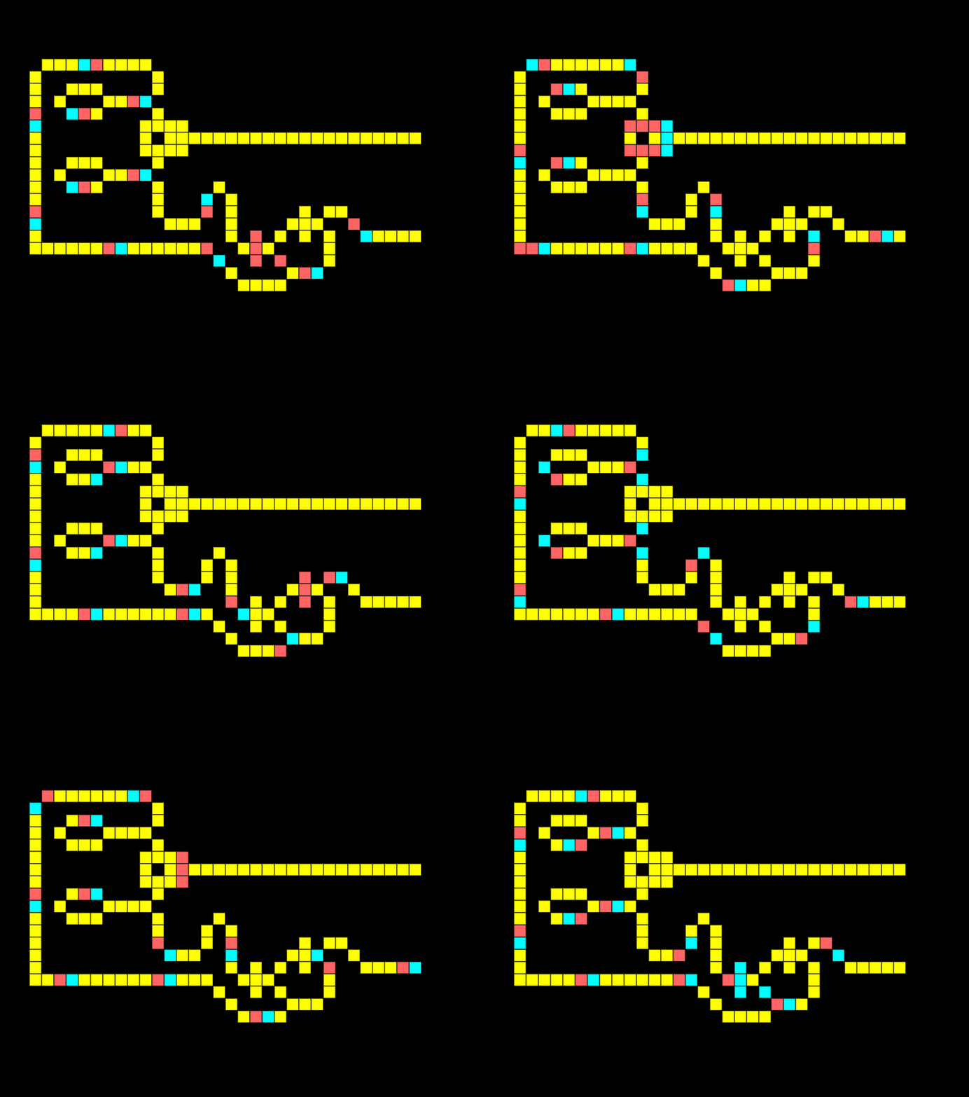
Theoretically, we could go ahead and build a computer from this, I won’t take the blog that far the half-adder was tough enough! But if anybody creates something cool using the repository let me know, I would love to hear it.

