In this blog I go over the different logic gates, the boolean expressions representing them and?how to create the various circuits from scratch. I plan to create an 8 bit computer in future blogs, but first I need to revisit the basics, so let’s learn together.
AND gate
The logical AND gate is written as AB in Boolean algebra. The result is true only if both A and B are true.
| A | B | Result |
| 0 | 0 | 0 |
| 0 | 1 | 0 |
| 1 | 0 | 0 |
| 1 | 1 | 1 |
Below is the AND gate using Logisim Evolution (A brilliant free tool), notice that both inputs must be on for it to power the LED:
OR gate
The logical OR gate is written as A+B in Boolean algebra. The result is true if A or B are true.
| A | B | Result |
| 0 | 0 | 0 |
| 0 | 1 | 1 |
| 1 | 0 | 1 |
| 1 | 1 | 1 |
Below is the OR gate, notice only one input must be on for it to power the LED:
NOT Gate
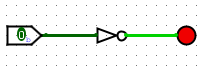
The NOT gate inverses the value. This is represented with a bar over the top: The NOT of A is A?:
| A | Result |
| 0 | 1 |
| 1 | 0 |
Below you can see that the input is 0 but it is powering the LED.
From these 3 gates, we pretty much have everything we need to create any of the other more complicated logic gates.
I’m going to create each of the following logic gates from the 3 gates we’ve just learnt.
NOR Gate
The NOR Gate (NOT-OR) gives a positive output when all the inputs are false.
| A | B | Result |
| 0 | 0 | 1 |
| 0 | 1 | 0 |
| 1 | 0 | 0 |
| 1 | 1 | 0 |
To create the circuit for this it helps to first create the boolean expression. The boolean expression is A?B? because the only time the result is true is when both A and B are not true. Let’s create this out of AND and NOT gates.
NOR is represented by the following gate (an OR gate with a circle at the end):
NAND Gate
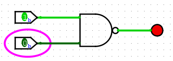
The NAND gate (NOT-AND) produces an output that is false only if all the inputs are true.
| A | B | Result |
| 0 | 0 | 1 |
| 0 | 1 | 1 |
| 1 | 0 | 1 |
| 1 | 1 | 0 |
Looking at each row where the result is 1 let’s create the boolean expression, this one is a little bit more involved.
In the first row the result is 1 and that is where both A and B are 0. This can be written as A?B?. The second row also has a result of 1, this is where A is 0 and B is 1, which equates to A?B. Finally, in the third row the result is 1 and that is where A is 1 and B is 0; AB?.
So the result is 1 when A?B? or when A?B or when AB?, which can be written as:
A?B?+A?B+AB?
Remember, + means or.
Below is an example NAND gate using NOTs, ANDs and ORs.
Don’t get overwhelmed, this is a verbose version just from using the boolean expression A?B?+A?B+AB?. Creating these circuits is akin to writing regex, it makes sense at the time, but trying to understand what you wrote last week is another kettle of fish.?
Let’s simplify the boolean expression A?B?+A?B+AB? and then make a simpler circuit.
- Apply the Distributive Law (Find what’s common, A? in this case)
- A?(B?+B)+AB?
- Apply the Complement Law (B?+B cancel?each other out)
- A?+AB?
- Apply the Absorption Law (AB+A? = B+A?)
- A?+B?
It helps to chuck your equation in this boolean algebra simplifier to get a good breakdown of the process.
So now we have a simple equation we can remake our circuit:
And of course, there is already a NAND gate we can use:
XOR Gate
The XOR Gate (Exclusive OR) gives true only when the number of inputs is odd, or in our two-input example, when only one of the inputs is true.
| A | B | Result |
| 0 | 0 | 0 |
| 0 | 1 | 1 |
| 1 | 0 | 1 |
| 1 | 1 | 0 |
Let’s write the boolean expression for this one. Remember to look at the Result column and find the ones with a positive output. The second row has a positive output and that’s when A?B. The first row has a positive output with AB?.
A?B+AB?

When you see A?B+AB? in a boolean expression this can be written as A?B. Below is the symbol for XOR.

XOR is a really important gate that we’ll use in future blogs to create a full adder.
XNOR
The XNOR gate (Exclusive NOR) is the inverse of the XOR gate. Note the difference in the truth table. It’s true when A and B are false or when A and B are true.
| A | B | Result |
| 0 | 0 | 1 |
| 0 | 1 | 0 |
| 1 | 0 | 0 |
| 1 | 1 | 1 |
This can be written as AB+A?B?.
The symbol for XNOR looks like the following:
Example circuit
The best way to learn how to create these circuits is to dive in and actually draw them out yourself.
Let’s create a random truth table which has 3 inputs, and from that we’ll derive the boolean expression then create the circuit.
To make sure you cover all the combinations of inputs A, B and C, count up in binary (The first row is 0, 0, 0 and the last is 1, 1, 1). Here there should be 2^3 (8) combinations.
| A | B | C | Result |
| 0 | 0 | 0 | 1 |
| 0 | 0 | 1 | 0 |
| 0 | 1 | 0 | 1 |
| 0 | 1 | 1 | 1 |
| 1 | 0 | 0 | 0 |
| 1 | 0 | 1 | 0 |
| 1 | 1 | 0 | 1 |
| 1 | 1 | 1 | 1 |
Find all the places where the result is 1, and combine them. Once you’ve combined them all have a go at simplifying the expression, you should end up with this result.
Next, we need to create the circuit. Once again I’d recommend actually writing this out on paper. Here’s my attempt:

Notice how I plug in the current state before each input of the logic gates, this allows you to verify what you’re doing/done.
Next, let’s create the circuit in logisim:
Which can be further simplified if we use a NOR rather than the not gates before the AND gate for A and C.?You might be thinking a NOR gate? wouldn’t a NAND be right in this scenario? Remember the result of A?B? is only true if A and B are false, a NAND gate would perform the NOT operation on the result of A and B, so this is true except for when A and B are true. A NOR gate is the NOT operation on the result of A OR B, so this is only true when A and B are false, exactly what we need.


Pingback: Wireworld - Cellular Automaton - Codeheir